

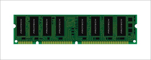
This Illustrator tutorial will teach you how to draw a nice looking vector RAM (memory chip) in Illustrator. You will discover how to draw circuit board, memory chips, circuit lines easily in this tutorial.
1. Drawing the RAM’s Circuit Board
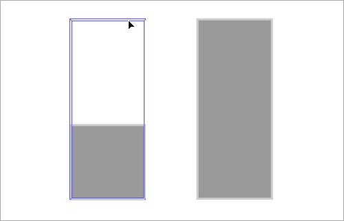
1. Lets start by creating the circuit board. Grab the Rectangle Tool. Draw the base of circuit board of the RAM. Use the transform values. I will call it “Base” for the sake of simplicity.

2. Draw another rectangle on top of the base. Align it horizontally with the base layer. Select both layers and in the Align Panel choose Horizontal Align Center button.

2. Punching Holes to the RAM
3. Select the Ellipse Tool and draw a circle shape that we are going to use to punch a hole in the circuit board.

4. Press Ctrl+U to turn on the Smart Guides. Smart Guides help us to align and move thing easily. Place it above the edge of the circuit board. Select the shape and align the center of the circle to the left edge of the board.
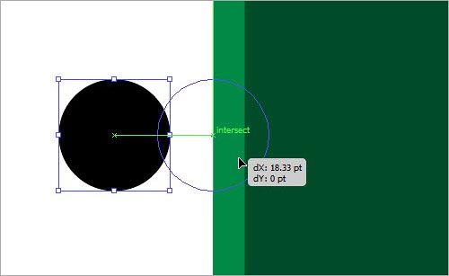
5. Select the shape, press “Alt” and drag to make a copy of the shape. Place it on the other edge of the circuit board.
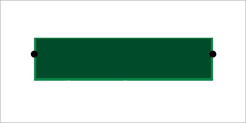
6. We will cut out the edge using the circle shape. Select the circle and Choose Object > Path > Divide Objects Below.

7. Select and hit delete the cut portion.

8. Cut out the other side as well. See the result.

9. Pick the Rounded Rectangle Tool. Click on the canvas to load the settings box. Enter values and Ok it.
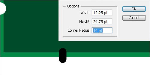
10. Duplicate by Alt+Dragging.

11. Select the and choose Divide Objects Below under Object > Path.

12. Cut a hole by deleting it.

13. We are going punch a 2 more holes in the board. Select the Ellipse Tool and draw a circle above the corner of the inner edge of the board.
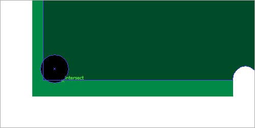
14. We need to make a hole on the other corner as well. Duplicate the original shape by Alt+dragging. Here is a simple trick to place the circle on the exact position on the other side of the board. Draw a rectangle that touches the edges of the circle and the board.

15. Select both shapes and duplicate. Right click and choose Transform > Reflect > Vertical. Align it with the right edge of the board. After it is aligned delete the rectangle. And the is in perfect location to punch a hole.


16. Both circles are perfectly set up. Use them to cut a hole just like we did earlier.

3. Creating the Outer Edge
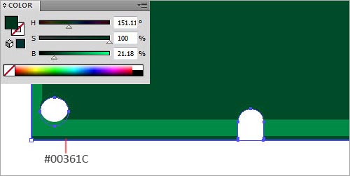
17. Let’s add some depth to the board. Select the outer shape of the board and duplicate. Hold “Alt” and drag downward slightly.

18. Choose a dark color.
19. Erase the edge with the Eraser Tool. Press Shift+E to select the Eraser Tool and run along the edge to delete.
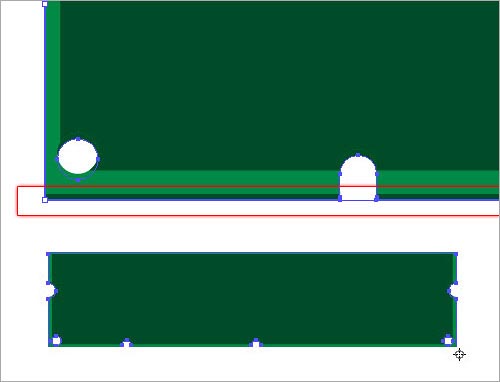
20. Here is the result.

4. Creating the Memory Chip
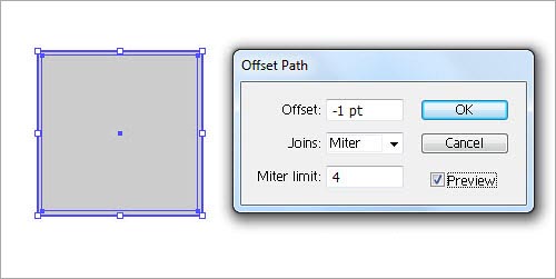
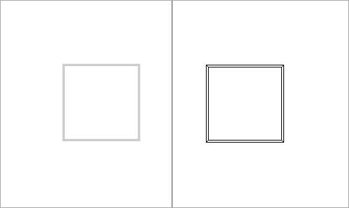
21. We are going to create a chip with beveled edges. It is quite easy to do using the basic drawing tools. Let’s start by drawing a square shape with the below dimensions. Choose a light gray color. We will recolor it later.

22. With the shape selected go to Object > Path > Offset Path. Enter the value and Ok.
23. Change the offset path color to a medium gray and lock down the object by pressing Ctrl+Alt+2.

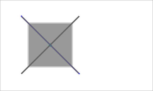
24. Pick the Line Segment Tool and draw a horizontal line that runs through the mid point of the square below.
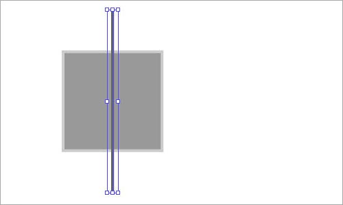
25. Press “R” key to select the Rotate Tool. Select the path, hold Shift key and rotate it by 45 degrees.

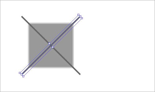
26. Rotate again. Hold the Alt key before you release the mouse to make a copy.
27. Select the path and choose Divide Object Below in the Path sub menu.

28. After completion, the object is divided into four pieces. The object we locked is not affected by this operation.

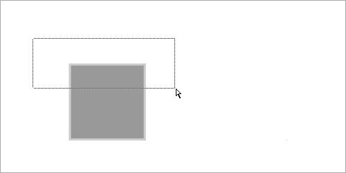
29. Now release the shape layer that we locked earlier. Press Ctrl+Alt+2. Select the shape and copy it by pressing Ctrl+C. Now select the shape and choose Divide Objects Below. This will cut out the pieces underlying pieces. Keep the four sides of the bevel and delete remaining pieces.

30. Now Press Ctrl+F to paste the shape we copied earlier. Now the shape of our chip is defined. We need to resize it.

31. Select the Direct Selection Tool by pressing “A”. Select the upper corners of the chip and extend upwards. And the chip is ready.
32. Place the chip above the circuit board.

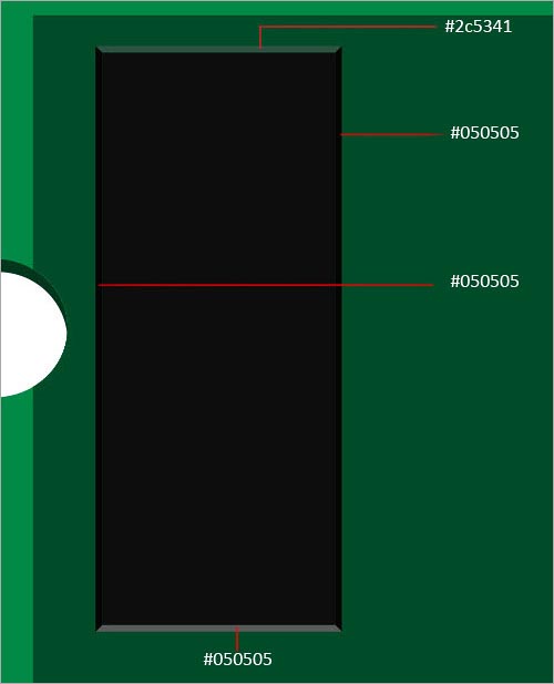
33. At this point we will recolor the chip.

34. Select and recolor each side of the bevel.
35. Select the chip and press Ctrl+G to group the chip. Duplicate the chip by Alt+ dragging. After the first copy is created press Ctrl+D to repeat the duplication. Crete 4 copies of the chip.


36. Select all the chips and duplicate.

5. The Chipset
37. Create some more chips. I have created different variations of the initial chip. We will fix these on to the circuit board. Don’t rotate the chips this will alter the lighting. To resize the chip select the edges with Direct Selection tool and increase or decrease the size.
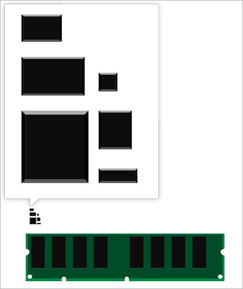
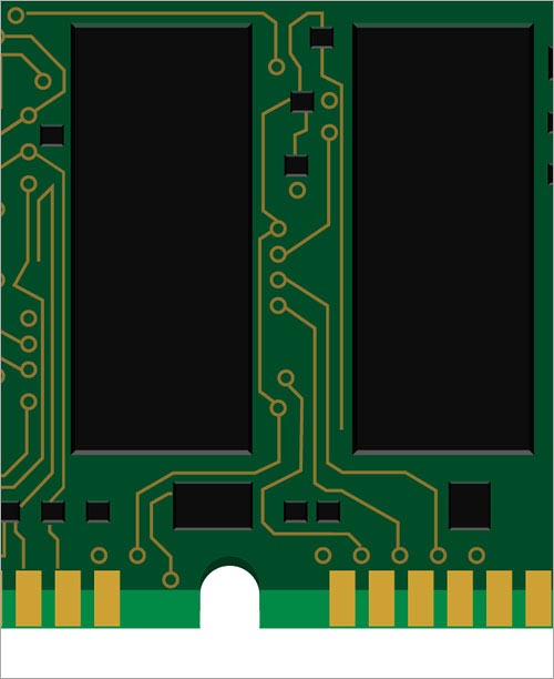
38. Start Adding chips to the board. Follow the steps.


39. Completed look.
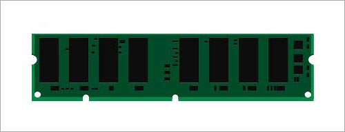
6. Creating the Chip’s Head
40. Create this shape using the Rectangle Tool. Select the shape and Alt+Drag to make a copy. Press Ctrl+D to repeat the process.
41. Finished result.

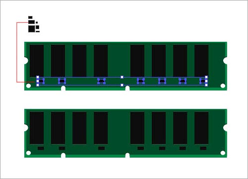
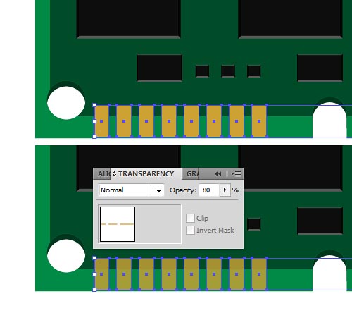
42. Select and delete the slots above the cut.
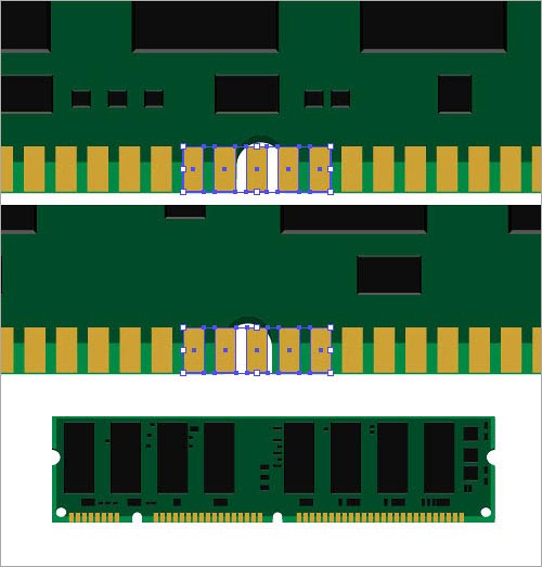
43. Select the all the slots and group them by pressing Ctrl+G. Reduce the opacity slightly.
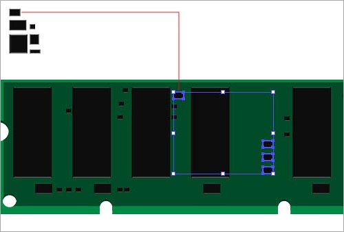
7. Drawing the Circuits
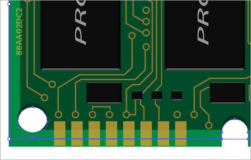
44. We are going to draw the circuits themselves. Circuits in a real PCB looks crazy with hundreds of connections. We will just mimic the pattern. We don’t need to create crazily weird circuits for this one! We can simply create them with the Pen Tool and by some observation. Let’s start drawing. First I put down some little circles and connected them using the Pen Tool


45. Continue to draw. Working from left to right.


46. You aren’t required to create the circuits exactly like this! Follow your intuition and ideas to draw even better.

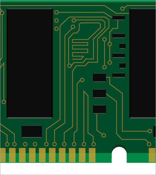
47. Finish the remaining.
48. Here it is so far.

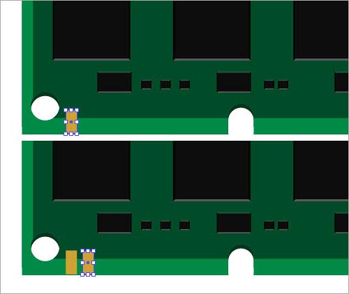
7. Adding Board info
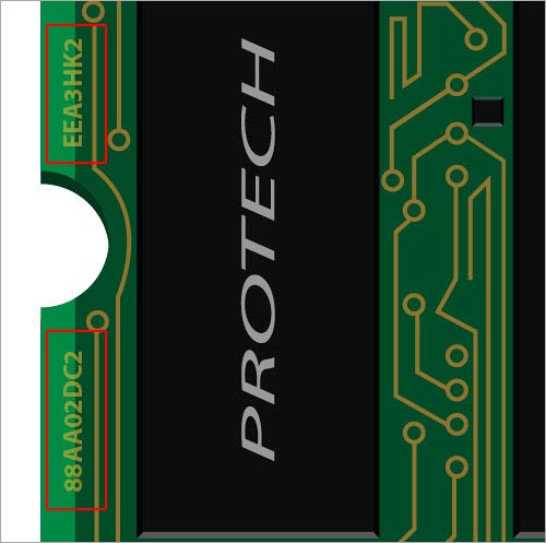
49. Let’s add some simple dummy info about the board. Name, Serial No etc. Simply typea name and rotate it with the Rotate Tool(R). Place It above the chip.

50. Duplicate the name on other chips. Use Align Panel to align each name correctly with the chip.
51. Add some more information to it.

8. Finishing Off the Memory Chip
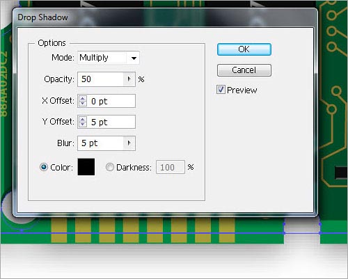
52. Select the outer edge of the board. Go to Effect > Stylize > Drop Shadow.
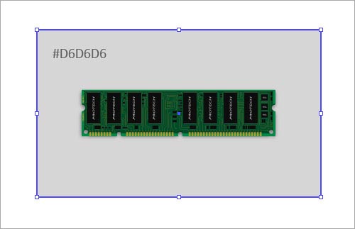
53. Draw a rectangle shape behind the RAM.
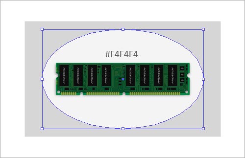
54. Grab the Ellipse Tool and draw an oval shape.
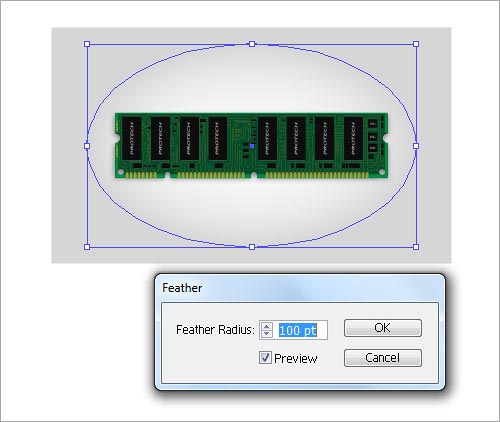
55. Apply Feather to the oval. Go to Effect > Stylize > Feather.
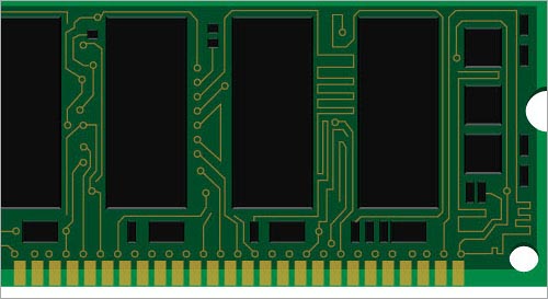
56. Apply some Gaussian Blur to blend it smoothly. And that concludes our design. We just finished it!

To download the source file for this tutorial, you will need to login as a member.
Sign up today to access all exclusive members content!

Awesome tutorial! Very detailed. Thanks!!!
Great work anna.. it looks like real image
Great tutorial, very detailed! Thx
This is incredibly intricate. Nice work!
Amazing works!!! Very interesting.. Your blog is a great one and i so love it! thanks!
great work ! Thanx for sharing
Thanks for the tutorial. Here is my version of the pc ram chip.
http://img.photobucket.com/albums/v645/duceduc/themes/pc-ram-chip-vector.png
These are truly impressive ideas in regarding blogging.
You have touched some good points here. Any way
keep up wrinting.
whoah this blog is wonderful i love reading your articles.
Keep up the great work! You know, a lot of persons are looking around for this info, you can aid them greatly.